Tuesday 18 February 2014

Motor Deconstruction

We were given a motor to disassemble, We did and noted each part as we progressed, Looking at the materials, manufacturing process and usage. Some of the parts included armature, brush contacts, permanent magnets, worm and wheel as illustrated below.

Displaying photo.JPG

We recorded features of each component on separate sheets, stating their use, material and method of construction and estimated values as shown in the picture below.


Displaying photo.JPG

After examining each part we then re assembled he component together and worked on a computer mouse which we did the same. attached is the disassembled mouse.

Displaying photo.JPG


Tuesday 11 February 2014

Precision measurements.

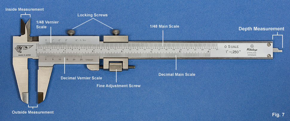
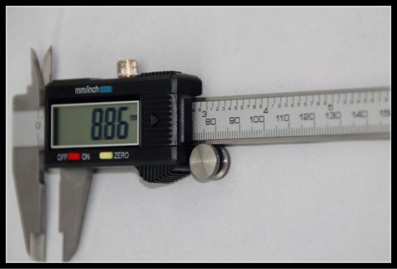
We were taken through precision measuring instruments, mainly Micrometers and vernier callipers which have accuracies of  0.01 and 0.02 millimetres. We went through the steps of how to read the instruments during measuring. The digital vernier calliper anyway is more accurate as the reading is displayed and just read straight away. A vernier calliper measures round and flat surfaced items and there are different sizes for different diameters, e.g One can measure from 0 - 25 mm and the other from 25 - 50 mm. Vernier callipers also measure the same and the include Depth and internal diameters. Below are pictures of the instruments we used. Before using the instruments they have to be zeroed first and lock them after measuring to ensure accurate answers.

Top.  Vernier calliper.          Middle. Micrometer.      Below. Digital vernier calliper.

.


Later i drew a bracket using third angle projection and  used the micrometer and vernier calliper to measure its dimensions to label the drawing correctly as per the evidence below.


Monday 10 February 2014

Bridge construction. {structures}

We were issued with materials to construct a bridge which would hold a reasonable load. we started by sketching how the bridge might look like as in the drawing below.


We built it using the straws, cello- tape and blue tack. there was also a string to suspend the weights during the testing of the bridge. This bridge out classed other groups work by carrying more load because it had triangular supports which made the base to resist bending forces to a larger extent.
1. Bridge constructed from the above sketch. (Burmese bridge)

2. This is what we did to reinforce the bridge underneath as at the top to increase its weight carrying capacity. 

The idea of just only reinforcing the initial bridge was because we had learnt that the height or depth of any item improves its stiffness or strength against sagging due to load applied. we had calculated two examples of moments of inertia in class. This made us to realise that even though the bridge can be narrow, with the reinforcements making the structure deep and tall enough, it would manage to support more load. It finally did so supported by the class calculations below.  


 This is to show dimensions of the bridge.


4. The bridge in three dimensions.
  

This bridge (Burmese bridge) carried the heaviest load than all .bridges built by other groups as verified by the facilitator's results after testing all bridges. results can be viewed through the link below.